
EOT Crane Wheel Assembly: Design, Load Calculation and Material Specifications
Modern crane technology is advancing rapidly, and crane wheel assemblies are at the center of this evolution. Wheel diameters are becoming more compact, load capacities are increasing, and the variety of assembly configurations available today is broader than ever before.
This guide covers the most important aspects of EOT crane wheel assembly selection: the common assembly types, how to calculate wheel loads correctly, the right material for each duty class, and a practical six-parameter selection framework. Whether you are specifying a new single girder EOT crane or a double girder EOT crane, or replacing worn components on an existing installation, this reference will help you make informed engineering decisions.
What Is an EOT Crane Wheel Assembly?
An Electric Overhead Travelling (EOT) crane wheel assembly is the mechanical system that supports and propels the crane along its runway rails. A complete assembly includes the crane wheel, wheel axle (shaft), bearings, bearing housings, end caps, and fasteners. The design and quality of the wheel assembly have a direct impact on crane stability, operational safety, and overall service life.
As crane structures evolve, selecting the right EOT crane wheel assembly becomes essential for reducing downtime, lowering maintenance costs, and keeping operations safe.
Types of EOT Crane Wheel Assembly
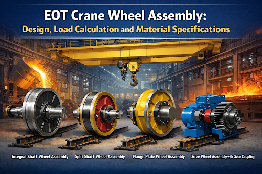
Modern lifting and transportation equipment uses several distinct wheel assembly configurations. Each type is suited to specific load conditions, maintenance requirements, and operating environments.
1. Integral Shaft Wheel Assembly (Fixed Axle Type)
The integral shaft type is machined or forged as a single unit, combining the shaft and the wheel in one piece. This construction produces a highly rigid assembly with excellent structural integrity.
- Best suited for heavy-duty and steel mill duty cranes operating under high static and dynamic loads
- One-piece construction eliminates the risk of shaft-to-wheel joint failure
- Replacement requires removal of the entire shaft assembly, which increases maintenance time
2. Split Shaft Wheel Assembly (Removable Axle Type)
In this design, the wheel and axle are manufactured as separate components joined by an interference fit or a mechanical lock. This modular approach simplifies on-site servicing.
- Wheels can be replaced without dismantling the entire end truck assembly
- Double girder EOT cranes commonly use this configuration for ease of field maintenance
- Lower lifecycle cost because only worn components need replacement
3. Flange Plate Wheel Assembly
The flange plate assembly uses a bolted flange connection between the wheel and the drive shaft or end carriage. This is a common choice wherever frequent wheel changes are part of the operating routine.
- Standard bolted connection allows fast disassembly without special tooling
- Flange mating surfaces ensure accurate wheel alignment during reassembly
- Single girder EOT cranes in workshop applications commonly use this configuration for quick repositioning
4. Drive Wheel Assembly with Gear Coupling
Long-span EOT cranes require precise travel synchronization across both end trucks. The drive wheel assembly incorporates a gear coupling between the motor gearbox output shaft and the crane wheel shaft, which allows slight angular and radial misalignment while transmitting high torque. This is standard on double girder EOT cranes with spans exceeding 20 m.
- Accommodates girder deflection in cranes with spans above 20 m
- Smooth torque transmission reduces structural stress on the bridge girder
- Standard specification for single and double girder EOT cranes with spans exceeding 20 m
EOT Crane Wheel Load Calculation
Accurate wheel load calculation is the starting point for every wheel assembly selection. Under-calculating wheel loads accelerates tread wear and causes fatigue failure. For a detailed breakdown of how load ratings affect crane selection, see our EOT crane load capacity guide.
Primary Load Formula
The maximum static wheel load P is calculated using the following formula as defined by GB/T 3811:
P = [(Q + Gt) x phi] / n + Gb / 2
Where:
- P = Maximum static wheel load in kN (the key input for wheel selection)
- Q = Rated lifting capacity of the EOT crane in kN
- Gt = Weight of the hoist and trolley assembly in kN
- phi = Dynamic factor: 1.1 for A3-A4, 1.2 for A5-A6, 1.3 for A7-A8
- n = Number of wheels per end truck (typically 2 or 4)
- Gb = Weight of one bridge girder in kN, divided equally per wheel
Minimum Wheel Diameter Formula
Once P is established, the minimum required wheel diameter is determined using the GB/T 7232 formula:
D >= C x (P)^(1/3) / f
Where:
- D = Minimum required wheel diameter in mm
- C = Material and hardness coefficient (12 to 18, lower values for harder steels)
- P = Maximum static wheel load from primary formula in kN
- f = Duty factor: A3 = 1.0, A5 = 0.8, A7 = 0.63, A8 = 0.50
Round the calculated diameter up to the nearest standard size: 200, 250, 320, 400, 500, 630, 710, 800, or 900 mm.
Tread Contact Stress Verification
After selecting the wheel diameter and rail type, verify that the Hertzian contact stress at the tread-rail interface does not exceed the allowable limit for the selected material and hardness grade. This step is particularly important for A6-A8 duty class cranes operating at high cycle frequencies.
EOT Crane Wheel Material Specifications
Choosing the correct wheel material is one of the most important decisions in the wheel assembly selection process. The material determines tread hardness, contact fatigue life, impact resistance, and heat treatment response. Using a lower-grade material for the actual duty class is the most common reason for premature wheel failure.
Cast Steel (ZG340) – Light Duty
Suitable for low-frequency, light-load applications in A3-A4 duty class service. ZG340 cast steel is a cost-effective option, but cannot accept effective surface hardening, which limits its tread hardness and fatigue life. This grade is rarely specified in new crane designs today.
- Recommended for: A3-A4 duty class, low-frequency operations
- Not suitable for cranes requiring effective rim quenching treatment
55# and 65Mn Medium Carbon Steel – Standard Duty
These are the most widely used EOT crane wheel materials for standard industrial applications. Both grades respond well to rim quenching heat treatment and can achieve tread hardness in the HRC 38-43 range at adequate penetration depth. 65Mn includes added manganese, which improves hardenability and wear resistance.
- 55# steel: standard choice for A3-A5 duty class cranes in general workshop environments
- 65Mn steel: preferred for A5-A6 applications where improved wear resistance is required
- Both grades achieve the minimum tread hardness depth of 20 mm with rim quenching
42CrMo Alloy Steel – Heavy Duty
42CrMo is the preferred material for heavy-duty and metallurgical crane applications, including steel mill duty cranes. Its superior hardenability allows tread hardness of HRC 42-48 at penetration depths exceeding 30 mm. The high core toughness absorbs impact loads from abrupt starts, emergency braking, and end truck skewing.
- Duty class: A5-A8, including metallurgical and foundry cranes
- Tread hardness: HRC 42-48 at depth greater than 30 mm
- Recommended for cranes subject to high cycle frequency and impact loading
50CrMo Alloy Steel – Extreme Duty
50CrMo is specified for the most demanding operating conditions, including continuous heavy-cycle service and high-temperature foundry environments. The higher carbon content pushes surface hardness to HRC 45-50, delivering maximum contact fatigue resistance.
- Duty class: A7-A8 continuous service and extreme-temperature foundry cranes
- Tread hardness: HRC 45-50
- Highest contact fatigue resistance in the standard grade range
Heat Treatment Requirements
All crane wheel treads require surface hardening treatment. Rim quenching is the standard method, producing a hardened surface layer while maintaining a tough core. The tread hardness must not be set too high, as excessive hardness creates brittleness and promotes surface cracking. A minimum hardened depth of 20 mm is required for extended service life across all duty classes. SBE Crane supplies material test reports with every wheel assembly shipment.
How to Select the Right EOT Crane Wheel Assembly
Correct wheel assembly selection requires evaluating six engineering parameters against the actual operating conditions of the crane. An error in any one of these parameters can result in premature failure, unplanned downtime, or unsafe crane operation.
Parameter 1: Wheel Load (P)
Always calculate the wheel load P using the formula above before specifying any wheel assembly. For cranes above 20 t rated capacity, never estimate P from experience alone. Refer to our EOT crane load capacity guide for further reference on how rated capacity translates to actual wheel loads.
Parameter 2: Rail Type and Profile
The crane wheel tread width must be matched to the rail head width. Common crane rail types – QU70, QU80, QU100, and QU120 – correspond to increasing wheel load ranges. A mismatch between rail head width and wheel tread width is the primary cause of edge cracking on both the rail and the wheel tread. The rail head width should be at least 10 mm narrower than the wheel tread width.
Parameter 3: Duty Class (Work Class)
The crane duty class, defined as A3 to A8 per GB/T 3811 or M1 to M8 per FEM, determines the required wheel material grade, minimum heat treatment depth, bearing rating, and fatigue life in load cycles.
- A3-A4: 55# medium carbon steel
- A5-A6: 65Mn medium carbon steel
- A7-A8: 42CrMo alloy steel
Parameter 4: Operating Environment
Standard indoor workshops require general-purpose sealing and standard grease. Outdoor exposed yards require enhanced sealing against moisture and dust. High-temperature foundry environments (ambient above 60 degrees C) require special high-temperature grease and C3 bearing internal clearance. Corrosive or explosive-risk zones require application-specific sealing and material specifications.
Parameter 5: Travel Speed
EOT crane travel speeds above 60 m/min require dynamically balanced wheel assemblies, tighter bore tolerances, and premium bearing grades to prevent vibration and premature bearing wear. High travel speeds also reduce allowable contact stress at the tread-rail interface, factored through the dynamic coefficient phi in the load calculation formula.
Parameter 6: Span and Girder Deflection
Double girder EOT cranes with spans above 20 m experience significant girder deflection under full rated load. This deflection introduces angular misalignment at the wheel shaft. Wheel assemblies for long-span cranes must incorporate gear couplings between the gearbox output shaft and the wheel shaft to absorb deflection and protect the crane drive system.
EOT Crane Wheel Assembly Maintenance
A planned maintenance programme for the wheel assembly extends crane service life and prevents unplanned operational stops. For a complete maintenance schedule covering daily, monthly, and annual checks, refer to our EOT crane maintenance checklist. The following four areas require regular inspection.
Tread Wear Inspection
Inspect the wheel tread at regular intervals and replace the wheel when tread wear exceeds 15% of the original tread thickness. Operating a worn tread beyond this limit causes progressive rail damage and increases the risk of derailment.
Bearing Lubrication
Lubricate wheel assembly bearings at intervals based on operating hours and ambient temperature. Inadequate lubrication is the most frequent cause of premature bearing failure in crane wheel assemblies. Use the correct grease grade for the operating temperature range.
Wheel Flange Condition
Side wear on the wheel flange is a reliable indicator of rail misalignment or crane skewing. Before replacing a worn flange, inspect and correct the runway rail alignment. Replacing the flange without correcting the alignment will result in rapid wear of the replacement component.
Abnormal Noise and Vibration
Rumbling sounds or periodic vibrations from the end truck are early warning signs of bearing deterioration or wheel out-of-round. Investigate these symptoms promptly. For replacement components, visit our EOT crane spare parts page.
Conclusion
The EOT crane wheel assembly is a core component of any overhead crane system. Getting the selection right requires accurate wheel load calculation, correct material specification for the duty class, proper rail matching, and an assembly type suited to the maintenance requirements of the application.
Whether the application calls for a heavy-duty integral shaft assembly for steel mill duty service, a modular split shaft design for ease of maintenance on a double girder EOT crane, or a gear-coupled drive wheel assembly for long-span synchronized travel, each parameter must be evaluated against actual operating conditions.
SBE Crane supplies a comprehensive range of EOT crane wheel assemblies to suit diverse industrial requirements. For technical specifications, custom orders, or engineering consultation, contact us or email us at sales@sbecrane.com.

Founded in year 2002 by Mr. Rajan K Nair, who has been the backbone of the firm for the past 25 years with his vast experience of more than 30 years with designing, manufacturing, refurbishment, erection and commissioning of all kind of material handling equipment’s. .. Read More